Dipole Antenna (dipole aerial)
The dipole aerial (Dipole Antenna, DP, and doublet antenna) often seen is antennas of 1/2 wavelength in the power feeder that squarely applied two of about 1/4 wavelength leads (element) to the power feeder. It is the most basic one in the tuned antenna.
It is an antenna that an amateur wireless family of us often makes by oneself. If the principle of this antenna is understood well, other tuned antennas can be easily understood.
Feature of dipole aerial
The dipole aerial is a kind of the resonant antenna, "Di" is the meanings "Two". It is ,in a word, an antenna in two poles. It usually uses by 1/2 wavelength, and there is a dipole aerial of one wavelength, too.
Length of dipole aerial of 1/2 wavelength (λ) (shortening rate)
It actually becomes inductivity (L character) a little when it is 1/2 wavelength though the dipole aerial of the length of 1/2 wavelength (λ/2) is a fundamental form of the antenna, it shortens a little actually (Shorten it), the feeding power point impedance is made pure resistance, and it uses it.
The shortening rate grows by the lead (element) fat. In a word, it shortens more than the calculation values by fat. Generally, it shortens by about 2-5% and it uses it. Moreover, the shortening rate grows if the coating lead is used, and the conductor is shortened further.
The resonance frequency of the antenna is examined by using dip meter (Dip Meter) and the SWR meter (standing-wave ratio measuring instrument and Standing Wave Ratio Meter) for the length of the element to measure to be suitable accurately.
Misunderstanding of shortening rate of antenna
The shortening rate is a shortened ratio and no shortened ratio. If it is shortening rate 2%, 2% or 0.02 becomes the shortening rates. If the bigness and smallness of the shortening rate is discussed, it is necessary to use this.
This should be expressed though it might be displayed as 98% and 0.98, not the shortening rate but "Shortened ratio".
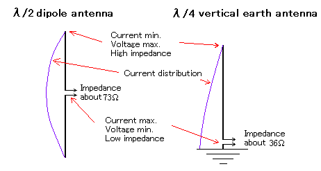
Voltage and current distribution of λ/2 dipole and λ/4 vertical earth antenna

The voltage in the element of 1/2 wavelength dipole antenna becomes the maximum in both ends, and the current becomes 0 earlier than it because it doesn't flow. Moreover, the voltage becomes in the feeding point and the currents become maximums lowest.
This operation is basic of the tune type antenna. Similarly, it becomes 0 in the current in the maximum voltage in the point in the dipole aerial of one wavelength. It will feed power from the point of the maximum voltage and the lowest current, and the device is necessary for feeding power if it feeds power from the center.
It is thought that there is the lower half of the vertical dipole antenna of λ/2 under the soil for the vertical earth antenna of λ/4.
Impedance of λ/2 dipole and λ/4 vertical earth antenna
The feeding power point impedance of the dipole aerial of 1/2 wavelength becomes about 73Ω. Therefore, the coaxial cable of the characteristic impedance 75Ω (5C-2V etc.) was often used by the power feeder.
It is the one that such a thing doesn't worry in amateur radio and I also fed power directly with the coaxial cable though Balin (Balun) is used for here because the coaxial cable is no balance type's power feeder.
If the angle of about 120 degrees is put without putting the dipole aerial straight putting it, the feeding power point impedance becomes about 50Ω. One Paul was put up at the center with the antenna of shortwave belt (HF), and the antenna that arranged the element in reverse-V type was often used. The coaxial cable of 5D-2V(50Ω) was often used by this power feeder.
The feeding power point impedance of the vertical earth antenna of λ/4 becomes half about 36Ω of the λ/2 dipole.
Directivity and gain of λ/2 dipole antenna
If 1/2 wavelength dipole antenna is horizontally put, it becomes the electric wave of the horizontally-polarized wave. The directivity in a horizontal plane at this time becomes letter of eight.
Moreover, if this is vertically put, it becomes the electric wave of the vertically-polarized wave. The directivity in a horizontal plane at this time disappears, and the electric wave is radiated uniformly in the horizontal all directions.
The gain becomes about 2.15dBi based on a virtual antenna (It is called Isotropc Antena) that uniformly radiates both vertical horizontal planes. Moreover, making the standard of the gain the dipole of 1/2 wavelength becomes 0dBd in this case a lot.
Application of dipole aerial
There is only being said that 1/2 wavelength dipole antenna is a basis of the antenna, and the application of this antenna extends to many topics.
- Miniaturization antenna with loading coil
- Method to operate by two or more frequencies by installing two or more elements in parallel
- Method to operate by two or more frequencies by installing parallel resonant circuit on the way of element, and separating element after the future electrically
- It ..two or more dipole aerial.. feeds power at the same time and there are a stack antenna that earns the gain and an array antenna.
- One wavelength loop antenna is a transformation of two step stack of 1/2 wavelength dipole antenna.
- It is thought that Yagi Antenna is a transformation of the dipole aerial.
- J type antenna and Chepperin antenna that move the feeding point are kinds of the dipole aerial.
- Additionally, if the dipole, Discone-antena, HB9CV-antenna, T2FD-antenna, Qubical-Quad-antena, Swiss quad-antenna, and Dual loop-antenna, etc. are counted by return, it is boundless.