Experiment and practical use of UHF/VHF Rhombic-antenna
It produced it because the directivity wanted to be sharp, the gain to be also comparatively large, and to experiment on Rhombic-antenna of wideband with the traveling-wave antenna after all than before.
Outline of Rhombic-antenna production
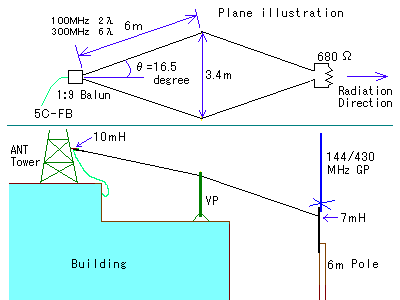
It becomes 6λ as 6m by 2λ and 300MHz in 100MHz the length of about one. It became about 12m in total length. It might be only I that receive the electric wave of the television with such huge Rhombic-antenna in all parts of the world, too. Will you get excited when thinking only one in the world? (Are there none of interests?)
If power is small, this antenna can be used to transmit amateur radio . It might be good for the communication between constant fixation bureaux of the direction. (144MHz,430MHz)
Manufacturing method of UHF/VHF Rhombic-antenna
Feature of Rhombic-antenna
Rhombic-antenna is an antenna that arranges the electric wire of the number of wave length (wire and element) in the diamond by the length of about one, feeds power from diamond one, and installed the terminator in the other. In general, the terminator is about 600Ω, and the feeding power point impedance is about 600Ω. It has a very sharp directivity from the feeding point in the direction where the terminator was installed. It was used for a long time for the sending and receiving of shortwave (HF).
It is the one that is called what made straight without putting out only the one side of Rhombic-antenna to the ground, and bending the element Beverage-antenna.
In general, 1/2λ dipole aerial, one wavelength loop antenna, and Yagi Antenna (1/2λ) often used tune by the element, and have gotten on the element by the standing wave. However, Rhombic-antenna is a traveling-wave antenna (aperiodic antenna), and doesn't have the standing wave on the element. Because it doesn't have that the part where the voltage is especially high by there is no standing wave, the influence of surroundings is comparatively little.
The directivity sharpens by lengthening the length of about one, narrowing a diamond angle according to it, and making it long and slenderly. Even if the angle is narrowed, it is not significant when the length of about one is shorter than that of wavelength.
It becomes a vertically-polarized wave if it vertically puts it on the horizontally-polarized wave if the diamond is horizontally put. It horizontally put it because it was a horizontally-polarized wave in case of this time.
Yagi Antenna is not too wideband, and .badness. becomes becoming of the performance when making it to wideband though a lot of Yagi Antenna in general is used because it is possible to do as wavelength is short and the antenna is small compared with HF in VHF it. Rhombic-antenna is the best for the reception originally very wideband and the television. Moreover, because the direction of the reception is decided, this is also convenient. However, it might be able to be said that largeness is a fault.
Another feature is that the loss occurs because there is a terminator. Be that the gain it falls that there is a loss. However, if the directivity is good, the gain manages to become it with the amplifier (booster) in the reception.
Plan and diagrammatic elevational view of Rhombic-antenna put to practical use

Figure above is a plan, and figure below is a diagrammatic elevational view. The roof tower in the rooftop in the deck is made a feeding point, and the center part of the electric wire (element) is supported by two places with mast and the roof horse of the vinyl pipe of 2m. Height from the ground is about 7-10m. Feeding power is 75Ω coaxial cable of 5C-FB.
Balun in the feeding power part is putting it in a plastic case with a waterproof mixer for the television reception. The terminator is put in the film case with the useless article. The terminator is 680Ω1/2W.
The element was torn a usual 1.25mm2 vinyl code, made to one, and used. It is convenient to hardly need the the cost of materials.
Balun's (impedance converter) schematic diagram and way of making

The feeding power point impedance of Rhombic-antenna is called about 600Ω. The impedance converter of 1:9 compared with impedance is necessary to feed power with 5C-FB(5C-2V) etc. of 75Ω.
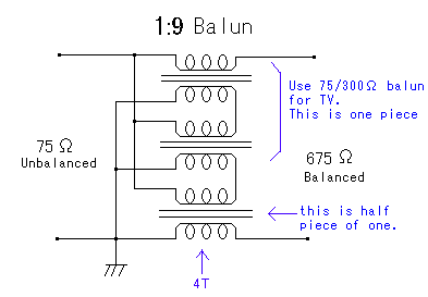
Two converters of 75Ω-300Ω for the television reception are prepared. It is the one that is called a glasses core. It wires for this by using a couple and the half as shown in figure. When Balun of 1:9 compared with impedance can do, it puts it between the coaxial cable and the antenna as shown in the plan above.
The impedance transformation of 75Ω and 675Ω and no equilibrium is converted by this (BAlUN, BALanced-UNbalanced).
1:9 Balun's ideas compared with impedance
Balun's wiring is understood well when thinking as follows though seems to be complex seemingly.
1:1 three Balun is prepared, it wires for the first side, and it wires the series for the second side in parallel. 1:3 step-up transformers compared with the voltage are completed by this. In a word, it becomes 1:9 Balun's completions compared with impedance.
Result using UHF/VHF Rhombic-antenna
Anyway, it operates well even if it negligently makes it though it is a huge antenna. I have been using this for about 20 years. It is a boast that it is cheap, lasts long, and the performance is good. The feature is not to see the antenna of the television.
| Gain |
Compared with eight element Yagi It is +3 - -3dB in 100MHz-200MHz. Compared with 14 element Yagi It is -6dB in 500MHz-600MHz. In a word, the gain seems ten element Yagi and equal. |
|---|---|
| Directivity |
Directivities seem to be sharper than Yagi Antenna of about ten elements. The angle θ of Rhombic cracks in 200-600MHz the directivity and in 30-40 degrees, is no use. When this angle is reduced, it is improved from the vicinity of 200MHz. It is unquestionable even for the vicinity of 600MHz in the θ=16.5 degree. I think that you should reduce the angle more if it uses it for the vicinity of 800MHz. However, the sidelobe might go out in the vicinity of 100MHz. |
| Band |
If 100MHz-600MHz performance is sacrificed to some degree, it is 50MHz-1000MHz. |
| Another |
The polarized electromagnetic radiation side becomes a horizontally-polarized wave if it horizontally puts it. It becomes a vertically-polarized wave if it vertically puts it. The resistance of 680Ω was adjusted to 0Ω by the mischief. There seemed especially to be no substantial change if it used it for the reception. It seems to operate well manage considerably even really. |