How to use of the Spectrum analyzer
Because it had borrowed the Spectrum analyzer from Rade Schwarz Japan Ltd. to measure outputting waveform of AM wireless mike, was used after a long time.
What is the Spectrum analyzer ?
Spectrum analyzer (Spectrum analyzer)takes the frequency in a horizontal axis (X axis), and is a measuring instrument in the spindle (Y axis) like to the oscilloscope that displays decibel (dB) as for the voltage or the electric power waveform. It is called for short. There is no distinction between the voltage and the electric power because it is decibel (dB) display. (For instance, it is ten times in the voltage, and 100 times in the electric power in case of 20dB. )
It is a measuring instrument that can see the frequency element to be brief. It is called a spectrum analyzer.
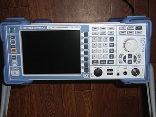
Spectrum analyzer FSL18 of Rohde&Schwarz

This photograph is Spectrum analyzer FSL18 borrows from Rade Schwarz Japan Ltd. through the CQ publisher.
It is not like being able to buy it privately very much because it is the expensive one.
WidowsXP stands up when switching on, and this is a computer. It is not when trying though it is likely to be able to use with the mouse if the mouse is put up. It operated it with a right cursor.
The main specification of FSL18 of R&S
- Range of frequency: 9kHz-18GHz
- I/Q recovery bandwidth: 28MHz
- 1.2dB of level measurement precision :< (With 18GHz. )
- Resolution bandwidth: 1Hz-10MHz(It is 20MHz by 0 spans. )
- Fast measurement:
Measurement speed: 80 sweeps/second(By 0 spans. )
The frequency counter: It is < 50ms in resolution 0.1Hz. - Various measurement functions: Gain measurement, AM/FM/PhiM recovery, and another power measurement and noise factor/by power sensor connection
- Size (W x H x D): 342.3mm 158.1mm 367.0mm(The steering wheel is excluded. )
- 8kg in weight :<
General usage of Spectrum analyzer
- It turns on power.
- A central frequency of the horizontal axis is decided.
- The spectrum space of the span is decided. At this time, the frequency in the left end is made to become to 0 or the plus.
- The setting that the frequency in the left end is subtracted is disregarded.
- The measured signal is connected with the input terminal.
- It is especially noted that as for the input impedance in the measuring terminal, there are a lot of one of 50 OHM in a high frequency in which the impedance match should be taken.
- It is easy to adjust the attenuator of a vertical axis and to see.
- It sets it responding for RBW(Resolution Band Width) (bandwidth of the IF filter of the Spectrum analyzer).
Outputting waveform of AM wireless mike measured with Spectrum analyzer

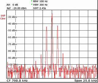
I want to do the design production AM and the one that the output of a wireless mike was measured with the Spectrum analyzer is this shape of waves.
It is the one that AM wireless mike was modulated by about 25% in the sine wave of 1.5kHz.
In this horizontal axis, a central frequency is 700kHz, the left end is 687.5kHz, and a right edge is 712.5kHz.
The level of the first upper and lower side-band wave of the plus or minus 700kHz1.5kHz is about -18 a dB compared with 700kHz signal carrier's level, and the theory street. It is for FM modulation element that in top and bottom of the next odd number side-band wave with level difference
The level of about the second side-band wave of the plus or minus 700kHz three kHz is about -40 a dB compared with the level of the first upper and lower side-band wave. I think this to be the one by the linearity of the modulation of the AM modulator and the one by residual FM the modulation element. However, there is no problem It is 1/100(Correspond to the distortion by 1%), and is an electric power, and because it is a voltage and 1/10,000 if it is -40 a dB. It is the very difficult generally one that makes to 1% or less at the distortion rate of the synthesis of the AM modulation.
Feature of Spectrum analyzer
- The electric power and the voltage of the transmitter pulse of the wireless machine and the transmitter are measured and spurious of that is measured.
- Local sending signal strength such as receivers and spurious of that are measured.
- It also uses it to measure electric field strength of the electric wave.
- It also uses it to measure unnecessary radiation strength of an electronic equipment.
- The input terminal is usually N type connector, and has the one that it is 50 OHM and is the impedance of unusually 75 OHM.