Production of RS-232C cable for THS710 oscilloscope
Because the RS-232C cable of the digital oscilloscope attachment of Tektronix had not been used for years, it lost. To take the shape of waves of the oscilloscope into the personal computer with the BMP file, this cable was made by oneself. The screen of the oscilloscope was taken in the photograph with the digital camera so far.
How to make RS-232C cable
The RJ-45 connector on the oscilloscope side used LAN cable as it was. The connector of nine pin D-Sub was installed in the personal computer side. I see as the following table only having cross it all, Except DCD and GND signals wire do not understand the connection method, and try and err
The setting of a digital oscilloscope did as follows.
EOL:LF
Parity:NON
Stop Bit:1
Delay:0 Sec.
Baud rate: 9600bps
It is ,in a word, a standard setting. The check comes in the place of the channel without permission reading the screen display channel of the oscilloscope when normally starting. The image taking is only clicked.
| Oscilloscope side(DTE) | Personal computer side(DTE) | ||||
|---|---|---|---|---|---|
| RJ-45(LAN cable) | Nine pin D-Sub | ||||
| Pin numbering | Color | Signal | Pin numbering | Signal | |
| 1 | White | Orange | DCD | 1 | DCD |
| 2 | Orange | DSR | 4 | DTR | |
| 3 | White | Green | DTR | 6 | DSR |
| 4 | Blue | GND | 5 | GND | |
| 5 | White | Blue | RXD | 3 | TXD |
| 6 | Green | TXD | 2 | RXD | |
| 7 | White | Tea | CTS | 7 | RTS |
| 8 | Tea | RTS | 8 | CTS | |
*The orange color and greens are replacements OK of all.
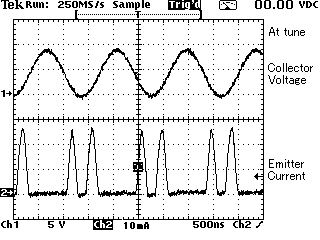
Image that uses and takes this cable

Software used to capture images of the free ones. Even better if you can process the cable, it works easily. I was not working quite well over the resignation. I was impressed when it works.
This shape of waves is a waves of the end step transistor of AM wireless microphone. The BMP file was converted into the GIF file further.
It is not necessary to photograph the oscilloscope image processing may be longer. But after this, broke this scope.