Production of off timer at 30 or 60 minutes that used PIC
The power supply of the turned-off television set worked in remote control, and it did not enter, and an off timer did not work without permission having of the microcomputer of the television that I was using in the bedroom trouble. Because the television was old, it was not possible to become a mended nature and the state as it is.
Production of off timer that uses PIC12F629
Because it had come to manage to use the PIC microcomputer, the off timer that was able to be used also for the television by holding the study of PIC concurrently was made. It introduces it because it made it to good. It made it with PIC microcomputer PIC12F629 by using the kit of solid-state relay (SSR) of moon Electronic commerce in autumn.
The Tera-Pad editor of free software made the program of the assembler of PIC. MPLAB IDE Ver.7.4 of the Microchip Co. and writing the PIC program handled AKI-PIC programmer Ver.4 in the moon to the PIC development tool in autumn.
Of course, the air conditioner can be able to use it besides the television because of the change in the radio, the radio-cassette, and time and changes of the cooling wheel. (2007.06.04)
Manufacturing methods of an off timer for 30 or 60 minutes
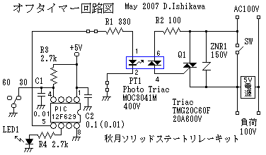
Schematic diagrams of an off timer for 30 or 60 minutes

Notes of production and How to use.
- Because a solid-state relay of the moon uses [fototoraiakku] in autumn, it is necessary to put the direct voltage. Moreover, the power supply of about 5V is necessary to make the PIC microcomputer work. These used the AC adaptor for the charge with the cellular phone that had become unnecessary. The voltage has been stabilized by the switching regulator in DC5V0.55A.
- When the cooling wheel is not installed in the triac, this solid-state relay SSR can be used only up to 2A in current. There is no problem at all without the cooling wheel this time because it is a television of about 100W. If the cooling wheel is put up, it is possible to use it up to 20A or less.
- Please install the fourth capacitors C1 of PIC12F629 in pin (GP3). It malfunctions easily because of the noise such as feeling after the terminal directly by the hand if the capacitor is not installed in the input terminal of PIC.
- The pin is not good at the fourth internal pull-ups of PIC in the input terminal (It is not possible to set it to the output). When it is a pull-up, an external pull-up resistor is needed without fail.
- The fourth pins become in an off timer for 60 minutes in H and it becomes an off timer by L for 30 minutes about PIC. This doesn't care about any voltage when operating only by checking it when starting.
- Pin (GP2) is a timer fifth output of PIC. A solid-state relay is driven directly. It flows by about 14mA. (The maximum rating of PIC is 25mA. )
- Pin (GP1) is the sixth output of PIC for the LED display. It connects it with LED through the current limitation resistance.
- Please set to all the outputs and give other terminals of PIC not used to me as opening.
- Watchdog timer (WDT) is not used. It is not necessary because it is reset that it uses it when the program stops and moves from the beginning.
- When the switch is made for 60 minutes for 30 minutes, the power supply of the middle switch is turned on, and the power supply of the middle switch is turned off soon, 100V power supply is supplied to the load. LED blinks once a second when making it for 30 minutes. LED blinks once every two seconds when making it for 60 minutes. LED blinks once a second when 30 minutes pass for 60 minutes.
- When not operating as an off timer, the power supply of the middle switch is left turned on.
- The power supply doesn't enter even if it blacks out after an off timer works and the power failure returns.
- 100V power supply of the load stops when the decided time of an off timer passes, and LED is turned off.
- The temporal precision becomes the accuracy of the internal clock of PIC. Because it was an error margin of 20 seconds, the plus will become the error margin of about 1% in 30 minutes in the thing that I produced. I think it is unquestionable in this extent in an off timer.
PIC assembler program
To assume an accurate timer program with PIC
It introduces the device to make it to the timer at accurate time as much as possible. The program is made by the assembler.
It is 2mS. The error margin of the subroutine of 500mS about puts the subroutine call and is +5μS. Accuracy in the program is 1/100,000 or less.
This is wrong though I assume the goto instruction to be one cycle written by Takao "Easy PIC microcomputer programming & electron construction" Takahashi of the Hidekazu system to which the program creation referred.
(PIC16F628 goto instruction is written one cycle on page 128. Moreover, it is an expression inarticulate when 250 though called 4μS*250=1000μS but 240 is set. If so, it will be 5μS*200=1000μS. )
(It is assumed 4*250=1000μS in the part where 1mS on page 248 in the article on the ramen timer (PIC12F629 is used) is made. Because the goto instructions are two cycles accurately, it is necessary to decrease one nop. )
As for PIC12F629 goto instruction, two cycles are correct. I see because of not becoming accurate time no matter how it experiments ..the examination thoroughly...
Moreover, it can make increasing cycle number by the first DLY_1 loop accurate time. It is because the error margin can be reduced because the loop frequency is limited within 256 because registers are eight bits in this if an error margin outside this loop is the same the time of the DLY_1 loop becomes long when cycle number is increased. Because this cycle number was assumed to be eight, it becomes 8*249=1992μS here in internal clock 4MHz because it is 1 one cycle = μS.
Next, the total of cycle bundled by ( ) in the first half number is 6μS when thinking about cycle when it makes a tour of DLY_2 number by six cycles. It becomes 2μS two cycles if eight cycles of an original DLY_1 part are excluded in the latter half. If the clock is accurate, it becomes accurate in total 2000μS.
DLY_500		;500mS
movlw	d'250'	;		2mS*250=500mS
movwf	CNT2	;
DLY_2	;2mS	;
movlw	d'249'	;	(1)
movwf	CNT1	;	(1)
nop		;	(1)
nop		;	(1)
nop		;	(1)
nop		;	(1)
DLY_1	;    DLY_1 loop
nop		;1	 1
nop		;1	 1
nop		;1	 1
nop		;1	 1
nop		;1	 1
decfsz	CNT1,f	;1	 2
goto	DLY_1	;2
decfsz	CNT2,f	;	 1
goto	DLY_2	;	(2)
return		;
Program of assembler of off timer
Assembler program for off timer
It is an assembler program that I made. Please make the file name timer30_60.asm etc. reading the editor the program part, preserve, and use it.
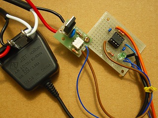
Completed substrate and peripherals

It is a wall adapter for the cellular phone charge for DC5V, and a timer substrate from the left from which everything used the SSR kit and PIC12F629 of the moon in autumn. It is a state before it encases it. The program of PIC is rewritten many times and IC socket is used to try.
When the timer is made from PIC12F629, an internal oscillation has hurried accuracy though you should use the selah lock or the crystal departure pendulum. Moreover, it is a charm that the circuit is very easy.