CS/BS received ideas of all rooms
![]() Isn't
not all tuners of communication satellite broadcasting and the satellite
broadcasts in the monger, and the CS tuner especially 1 a home even if it
is?When it tries to see this in each room, the number of tuners can do nothing
but be increased, and it is not general, and also costs cost.
Isn't
not all tuners of communication satellite broadcasting and the satellite
broadcasts in the monger, and the CS tuner especially 1 a home even if it
is?When it tries to see this in each room, the number of tuners can do nothing
but be increased, and it is not general, and also costs cost.
Outline and notes of receiving system
I had everything seen by the monger with only one CS(BS) tuner that was comparatively at a low price. In a word, the method of the mixture with the antenna system again was devised by modulating with the video and the audio signal of the CS(BS) tuner and converting it into UHF channel of the television.
UHF..signal..as it is..antenna..fly..think.A satisfactory image is not obtained by having flown with the antenna though it understands when trying.
The miso of this system is a thing to put the attenuator (attenuator). The knack of the adjustment is a thing that the modulation is not deepened. ..[bu]-.. sound (It is said the Buzz Richman sound) enters the voice when the modulation is put too much.
Please do not mix it with the input of the booster earnestly. The output is too large and it doesn't become something useful at all.
The image of VTR can be seen as an application even in the room without VTR.
System chart of monger of all CS/BS reception
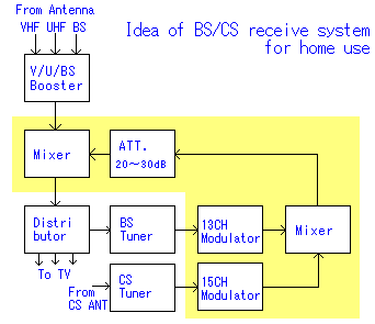
It is a part that a yellow part in figure added.
The modulator of 13CH and 15CH flies the signal of VTR sold for 4-5,000 yen in
the do-it-yourself store etc. with the antenna, and is things of the usage seen
in other rooms. It has not sold any longer now and obtaining might be difficult.
Because there is about 105-110dBμV, output a too large the way things are going, and unnecessary signal give a lot of obstructions to other channels, this antenna output puts the attenuator of 20-30dB.
The mixer is cheap if two distributors are used oppositely and enough for this usage.
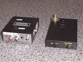
A left device is 13CH modulator. This seems to be 14CH originally modulator for North America, and it becomes 13CH in Japan. The high frequency oscillation circuit is steady for crystal. 13CH signal has come out in right side by pin Jack.
Because a right device became a switch of 14CH and 15CH, it used it with 15CH. The obstruction doesn't awfully become something useful with 13CH because it is adjacent if it uses it with 14CH. (Because not the residual sideband method but the both sides wave has occurred. )F type connecter was originally installed in the place where the antenna had adhered. The high frequency circuit is a self-excitation oscillation and it is necessary to fine-tune CH.