The heat radiation design method of the radiator (heat sink)
The method of designing the radiator of the semiconductor (cooling board)(heat sink) is the one that it is not understood to make the circuit privately easily. A suitable cooling wheel is put up, made to work, and, then, if it is not so hot, it is assumed it is good touching the cooling wheel.
Such a method wants to introduce the method of designing formal heat radiation though it might be acceptable.
What is thermal resistance?
Thermal resistance says the temperatures fluctuate a W between two points to which heat moves, and shows it is easy to transmit about heat. The unit is [ C/W ]. This concept of thermal resistance is used for the design of the radiator. It is a similar idea to the electrical resistance. Hot where correspondence's to voltage corresponding to current in the temperatures fluctuate between two points moves (lost electric power).

With pattern diagrams of left thermal resistance
Tj ---Junction (joint part) temperature of semiconductor
Tc ---Case temperature of semiconductor
Tf ---Temperature of radiator
Ta ---Temperature in air
θj-c ---Thermal resistance of semiconductor (transistor)
θc-f ---Thermal resistance of insulator and silicon grease
θf-a ---Thermal resistance of radiator
Then, the one that these thermal resistance was added is the entire thermal resistance (From the joint part of the semiconductor to the air inside) It becomes θj-a.
θj-a = θj-c + θc-f + θf-a
I do not think that you may consider even the thermal resistance of grease of the insulator or silicon so in the thing that the individual makes. Please consider it if it is not possible to disregard it because it is about 0.5-2[ degree C/W] title.
The entire thermal resistance θj-a and the collector loss (loss of heat of the semiconductor) The one that Pc was multiplied is temperature rise ΔT [degree C] of the junction. It is an ambient temperature in this The one that Ta was added is the junction temperature It becomes Tj.
ΔT = θj-a * Pc
Tj = θj-a * Pc + Ta
Please have room to lower enough than the maximum rating and design the temperature of the junction.
The calorific value of the semiconductor (collector loss Pc) can be easily calculated for direct current, and it is not possible to calculate easily in case of the switching element etc.The calorific value is counted backward measuring the temperature with the cooling wheel to understand thermal resistance at this time.
Computational method of thermal resistance of semiconductor (transistor) unit
Because the thermal resistance of the semiconductor (transistor) is not displayed in the standard table of the transistor, it is necessary to calculate from the standard table.
The example of the maximum rating in the standard table of the transistor is shown as follows.
Pc=25W(Tc=25 degree C) Tj=150 degree C
It solves and it is assumed that it became it. The junction of the transistor in this case and the thermal resistance between cases θj-c is calculated.
Time when the transistor works in the point of the maximum rating is assumed. Because the case temperature of the transistor that puts up an infinite ideal radiator is 25 degrees, the collector loss is 25W, and the junction temperature at this time is 150 degree C
θj-c = (150-25)/25 = 5 [degree C/W]
This becomes the thermal resistance of semiconductor (transistor) unit.
Thermal resistance of radiator (heat sink)
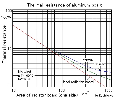
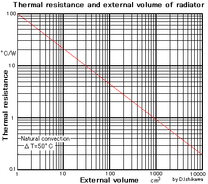
When the thermal resistance of the radiator (heat sink) is measured beforehand, the thermal resistance of various things is surmisable. The calculation graph of thermal resistance when the board made from aluminum is made a radiator and thermal resistance when thermal resistance depends on the external volume is shown as follows.
Thermal resistance of radiator (heat sink) made from aluminum board

It is a graph where the thermal resistance of the cooling wheel (heat sink) is calculated.
Attention. This is not a surface area of the cooling wheel. It is one side of the cooling wheel area.
When I am designing the television in the company, this has confirmed thermal resistance measuring it by the experiment many times in what actually used. This data is confident.
The graph that searched the Internet has been seen, and there seems to be data that has come below the ideal heat radiation board in this graph, too. Please note it.
Thermal resistance when depending on external volume

This is a radiator that there are a lot of ruggedness in the surface of the radiator (heat sink). It is a graph where thermal resistance for a splendid thing etc. made of aluminum on the market is calculated.
This graph is applied to the complexity for the board when depending on the external volume by bending it. This is the one having actually used it when I was designing the television in the company.
The external volume is a volume in which externals the outside of the radiator are connected. There are a lot of bends to the cooling board complex, and radiation fins and it applies to the thing etc.
This graph can be applied only when the temperature rise of the radiator is 50 degree C in the case of the natural convection. Please note the difference from this quite for the forced air cooling.
It is usual that thermal resistance grows more than this graph in an actual radiator when this graph is a natural convection, and heat radiation is an ideal.