Design and production of AM wireless microphone
From April 2005, I taught on a part-time lecturer at certain University of communications technology. In class, the AM transmitter and receiver to the computer using the CAD software production. This material is for AM medium wave wireless microphone (transmitter) so designed as circuit parameters have been determined to examine each.
It designed and produced only with parts on the market. I think that the performance finishes being practicable and be satisfactory. It introduces the device by the design and production.
Manufacturing method of AM wireless microphone
This AM wireless microphone can be united to a general-purpose substrate if it devises it if it is such a circuit though designed the printed wiring board with the computer in the class for the study of the substrate design.
Schematic diagram of AM wireless microphone
Easy movement of AM wireless microphone explanation
The audio signal of the electret capacitor microphone (about 10 0-mVp-p) is amplified to about 150-3000 times with TR1 and TR2. This audio signal is made the signal of the dynamic range of 4.5V.25V with emitter-follower of TR4, and the collector modulation in addition to the power supply of the circuit of the amplification of the electric power of C class of TR5 is multiplied. TR3 ..signal carrier of about 700kHz.. oscillates.
The current consumption of the power supply of no modulation is about 4mA in the circuit of TR1-TR3, and about 5mA in the circuit of TR5. About the antenna output voltage at this time was about 90Vp-p, and the output electric power was 10mW. It was possible to receive it anywhere in the house in a usual timbered house.
The voltage of about 90Vp-p hangs to the capacitor of C21, and, if possible, use the thing of 500V resisting pressure even by the thing of 50V resisting pressure, please though it operates. The cause of the defective operation was not understood and it had a hard time when producing it without knowing the thing of 25V resisting pressure mixed.
As for seeming that it is amusing that the capacity of C6 is larger than that of C8 in the schematic diagram above, the computational method of the bypass capacitor of the emitter is wrong. When the moving part of VR1 moves to the emitter side, the capacity of C6 is the twice or more C8 necessary.
Because the capacity of the capacitor did not expand the kind, it rounded it to the value that cutting is good as much as possible excluding the tuning circuit.
Design and the production of the transmitter, and it is trial and error and is devised things.
- That can be made only from parts on the market comparatively easily
- That often flies even if current consumption is a little electric wave and becomes practical use
- To be simple and to understand circuit easily
- That contains circuit as teaching material, and is significant
- Because the frequency variation greatly became FM modulation, it solved it by multiplying the collector modulation by the end steps though a base modulation and a direct collector modulation were multiplied by the oscillation circuit.
- The collector modulation to the oscillation circuit was extremely bad the linearity of the modulation, and did not become something useful at all.
- The final stage to operate Class A-AB, modulating the collector multiplying circuit including the bias circuit, and became very good linearity modulation characteristics, but this is inefficient final stage. so I stopped this method.
- I used 1-2m antenna lead. To efficiently carry a radio, found it good to be connected to a higher voltage circuit impedance and the antenna as possible.
7K coil (red core) for the local oscillation circuit used for the radio of the medium wave was used for the oscillation coil and the collector modulation circuit of the end steps to use parts on the market. It is the one that left figure resolves the coil and an inside structure was examined.
As for the number of the foot of the coil, in view of under, three numbers are put from the foot clockwise using it commonly. After it began to roll fourthly and it rolled it sixthly, the coil had been rolled in order of 1, 2, and 3. It connects between 4-6 with the collector circuit, and the antenna circuit is connected between 1-3. As for the rolling line ratio of the coil, the impedance ratio becomes about 1:90 10:95. Moreover, it is necessary to adjust the third pins to a hot side ,in a word, the antenna terminal side.
The inductance between 1-3 is about 360μH. It tunes it to about 700kHz with the capacitor of 150PF.
The antenna of about 2m is very thought to be high impedance as shown in figure.
The thing to raise the voltage supplied to the antenna as much as possible is like the knack. efficiently put out the electric wave
This antenna of 2m did equal operation to the capacitor of about 20PF.
Actual operation of end steps electric power amplification circuit of transmitter
The under of the voltage of the base is an emitter current (collector current) in this figure on.
It is an influence that the emitter current has decreased when the voltage of the base is measured in the shape of waves of the oscilloscope that applies the probe of the oscilloscope to the base.
It is time when the tank circuit in the end steps tuned it, and the collector voltage was ..0.. negative, and the current was 0 ..base drive.. in peak periods of positive. It is this that collector current decreases when tuning it
When the voltage of the blocked 4.5V hung on the collector side of TR5 when the amplitude did not modulate as shown in this figure, the collector voltage was 9.5Vp-p. The lowest value of the collector voltage swung up to a negative about 0.5V.
As for the adjustment of the tuning circuit, the collector current is made to become to the lowest.
When the tune is moved, the collector current (emitter current) becomes the maximum like this. It is the maximum peak value about 47mA in the screen of this oscilloscope.
Linearity of amplitude modulation of transmitter
This is a linearity of the AM modulation. I think that I do a so-so characteristic as a collector modulation.
A usual sound that was the wireless broadcasting and not inferior was heard though the modulation was multiplied in the music of the CS digital broadcasting, and it heard it on the radio of the medium wave.
Finished photograph of transmitter
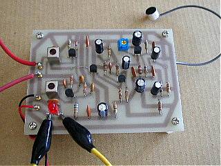
It was installed that LED and 270Ω resisted the power switch in parallel, and used it to adjust the tuning circuit in the end steps. It adjusts it in the place where LED darkens most. After it adjusts it, this circuit is detached or is short-circuited.
When the dry battery of 006P is used for the power supply, the electric wave doesn't get on the antenna if the lead wire that is called not only the antenna but also the earth side a counterpoise is not installed.
It seems that the pattern of the back is transparent because it is a glass epoxy board.