Method of identifying electronic parts
If only any or the value sees and parts such as the resistor, the capacitor, inductors, and transistors are not understood when the electron is constructed and when the appliance is repaired, it cannot be mastered. It is likely to be able to repair by understanding even only the main parts even if all parts are not understood.
Rules of values of parts (E12 affiliate)
It just drinks and I think the values of parts for a lot of things that are it not Ne, and an odd values of 1.2 Ohm or 6.8 Ohm to exist 1, secondarily, thirdly, and fourthly.
It is because the ratio becomes a problem in the selection of parts when the reason is designed by using parts. For instance, there is not a meaning even if there are parts of 1000 Ohm, 1001 Ohm, 1002 Ohm, and 1003 Ohm in the vicinity of 1000 Ohm though it is 11 Ohm, 12 Ohm, 13 Ohm, and 1 Ohm putting and you might exist parts in the vicinity of 10 Ohm either.
Parts used from such a reason well are E12 affiliates. It 1 , 1.2 , 1.5 , 1.8 , 2.2 , 2.7 , 3.3 , 3.9 , 4.7 , 5.6 , 6.8 , 8.2 It is the kind of one. drinking 12This progression is a geometric series of about 1.21 (geometrical progression). (101/12 = 1.21)
In most designs, these values are useful, and I think a design not good for the problem to often exist in the design in these values. However, there is a thing of the E24 affiliate, too, when a more detailed value is necessary by all means.
Even if the value is a little different it, a mass thing of the electrolytic capacitor etc. of the power supply is the one of unquestionable. Then, E6 affiliate (1 , 1.5 , 2.2 , 3.3 , 4.7 , 6.8) and E3 affiliate (1 , 2.2 , 4.7) are used for this case.
I think it is unquestionable in the E12 affiliate when privately producing it. In the production article, it often seems to be able to substitute it by often seeing the circuit by 560 ohms of the E12 affiliate though there seems often to be an example that uses 510 Ohm of the E24 affiliate. As a rule, I use only the thing of the E12 affiliate.
Pronunciation of color code
If this code is not understood, the values of parts such as the resistor, capacitors, and inductors cannot master parts by being being written by the color code or the numeric code. The following table is a color code table. Please see this table at first and remember little by little. It comes to understand momentarily of expecting will become accustomed.
| Color code table | ||||
|---|---|---|---|---|
| Color | Value | Multiplier | error margin |
|
| black | Black | 0 | 100 | |
| Brown | 1 | 101 | 1% | |
| Red | 2 | 102 | 2% | |
| Orange | 3 | 103 | ||
| Yellow | 4 | 104 | ||
| Green | 5 | 105 | ||
| Blue | 6 | 106 | ||
| Purple | 7 | 107 | ||
| Gray | 8 | 108 | ||
| White | 9 | 109 | ||
| Gold | 10-1 | 5% | ||
| Silver | 10-2 | 10% | ||
| None | 20% | |||
- Resistor
It is being written by the color code of treble-five digits. The treble is a multiplier in the figure even up to 1-2 digits for the treble and 4 digits. The fourth digit is an error margin. The fourth digit in figure is a multiplier even in one-treble for five digits. The fifth digit is an error margin. The unit is Ohm. It doesn't understand though there seem to be as many as six digits.
For instance, it becomes brown, black, red, gold, 10*102 =1000 and it becomes the one of the error margin of 5% by 1k Ohm.
- Capacitor
The pronunciation of the value is the same as resistance. The unit becomes PF. There is the one of not the color but the numeric code, too.
- Inductor
This is the same as resistance the pronunciation of the value. The unit becomes uH (micro Henry).
The pronunciation in the chip resistance etc. at two digit display.
| Sign | Value | Sign | Value | Sign | Value | Sign | Value |
|---|---|---|---|---|---|---|---|
| A | 0.1 | G | 1.8 | N | 3.3 | U | 5.6 |
| B | 1.1 | H | 2.0 | P | 3.6 | V | 6.2 |
| C | 1.2 | J | 2.2 | Q | 3.9 | W | 6.8 |
| D | 1.3 | K | 2.4 | R | 4.3 | X | 7.5 |
| E | 1.5 | L | 2.7 | S | 4.7 | Y | 8.2 |
| F | 1.6 | M | 3.0 | T | 5.1 | Z | 9.1 |
It is small, space that writes resistance exists the chip resistance etc. , and there is narrowly the one of two digit display such as "W3". "W" shows the figure, and "3" shows the multiplier.
- Resistance
"W" It becomes =6.8 and "3" = 103, and the unit is Ohm. It becomes 6.8*103 = 6800 = 6.8k Ohm.
Electric strength, value and error margin of capacity
| Electric strength[V] | Error margin | ||||
|---|---|---|---|---|---|
| Sign | Value | Sign | Value | Sign | Value |
| A | 1.00 | G | 4.00 | J | + or -5% |
| B | 1.25 | H | 5.00 | K | + or -10% |
| C | 1.60 | J | 6.30 | M | + or -20% |
| D | 2.00 | K | 8.00 | P | +100,-0% |
| E | 2.50 | V | 3.50 | Z | +80,-20% |
| F | 3.15 | W | 4.50 | ||
There is something displayed with the ceramic capacitor and the miler capacitor, etc. like "1H104M". "1H" shows the electric strength, "104" shows capacity value, and "M" shows the error margin of capacity.
- Electric strength
"1" shows the multiplier of ten, and "H" shows the figure of the electric strength. It becomes 1H = 101 * 5.00 = 50V.
- Error margin of capacity
"M" becomes M=error margin + or - 20%.
Method of identifying transistor
| Kind of transistor | |
|---|---|
| For 2SA type high frequency | The material of silicon (collector, base, and emitter) is the order of PNP. (PNP type) |
| For 2SB type low frequency | |
| For 2SC type high frequency | The material of silicon (collector, base, and emitter) is the order of NPN. (NPN type) |
| For 2SD type low frequency | |
Because the current flows from P type semiconductor to N type semiconductor when Mitibicayo is seen with the tester, the base is understood for the time being. How to distinguish the collector and the emitter does as follows.
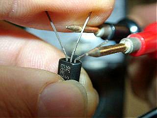
It explains as an example of the NPN type. The tester is set about 1000 time resistor range. A black stick (The plus voltage has gone out) of the tester is applied to the foot that seems that a collector it, and a red stick (this minus) is applied to the foot that seems that an emitter it as shown in the photograph. It touches between the foot and the base that seems that a collector it by the finger. If the needle of the tester swings more widely than the time usually applied only to the finger, the assumed foot is a collector and an emitter.
The PNP type reverses the color of the tester. As the application, it is possible to use to look for becoming complete hfe as it looks for hfe large, and it is possible to identify it simply from among transistors how many. The transistor understands and whether it is alive or dead is understood. I am always before using the transistor. I do not think that it knows and there is a disadvantage.
This forms an easy amplification circuit by using resistance the power supply of the tester and in the tester. The finger between the base and the emitter assumes the human body to be resistance and throws the current of the use base.
I think that analogue tester is good for this use.