Experiment and production of solar power generation
This is a method that the electric power company buys the surplus electricity to which daytime generated electricity though the solar power generation for the house is widespread recently around the newly built residential building. It costs cost and time to this method considerably large scale.
Motive of production of solar power generation device
I always thought whether there was usage that put out the maximum effect without so spending cost. The usage with the best solar panel is a way that uses the one that daytime generated electricity soon. I think that it is a usage that uses the energy of the solar panel to turn the below the floor level ventilation fan very fulfilled to the reason. However, because the electric power of the ventilation fan is originally small, the effect cannot be so expected.
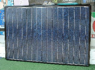
It decided to experiment by using this because the solar panel (40 number of power generation elements series) made by Mitsubishi Electric Corporation of the maximum output 126W, 19.2V, and 6.56A was obtained. I see ..no use quite.. though the result of the exploratory experiment output of the solar panel was put in the inverter for 24V direct. fall when the load ties the voltageTherefore, it made it to the method converted into 100V with the inverter while charging the battery for the car of 12V.
Manufacturing method of 12V battery electrical charge and discharge circuit
Circuit that charges with 12V battery
Left figure is a schematic diagram that charges with the battery for the car of 12V.
To prevent the overcharge of the battery, a fixed voltage system was adopted. The circuit is easy and an easy thing, etc. to maintain. a high thing and a fixed voltage system the voltage of the solar panel this
The circuit remodeled and made "Fixed voltage of precise class power supply kit for the laboratory" of Akizuki-denshi-tsuusyou. The remodeling part is a yellow part.
An important mistake is found in the circuit in this kit of the Akizuki-densi-tsuusyou. The emitter reversed with the collector of TR4 and the schematic diagram and the print pattern had reversed.
The spaces between the base and the collector operate as a diode even if the emitter is reversed with the collector. However, the meaning that uses the transistor disappears. The differential amplifier cannot be balanced and the temperature property must be not good either. 723 the fourth IC and the 5th input are connected with the base of the differential amplifier.
This kit was fairly sold ahead. The circuit was similarly wrong though there was an article on the kit of almost the same circuit as the CQ magazine of the November edition in 1992. It seems to use very the same substrate. How have for nobody to have noticed it to be up to now have done?
This kit has information that 723 IC oscillates easily when examining it on the Internet. Capacitor C1 and C2 during the power supply of 723 IC (12 pins) and earths (seven pins) have adhered at a considerable distance when the print pattern is often seen though I did not oscillate. I moved C2 near 12 pins of IC. -..SENSE.. - The person who lengthens the wiring for OUT thinks it is natural because it oscillates. It is basic to put the capacitor near the power supply of IC and the pin between earths of the design.
TR2 and TR5 use the transistor. There is a voltage descent and it doesn't become something useful as much as 8V in FET. The voltage descents with this circuit are two in IC of 723 transistors and are 2 transistors of TR2 and TR5, and it is an influence by the voltage descent between four base emitters in total, a diode of D4, and there is a voltage descent of at least 3-4 the V.
It is not in the schematic diagram, and doesn't need 10kΩ of R8. After that,
because the maximum current is 6-7A, the current limitation circuit is not
necessary. To decrease the voltage descent even a little, it deletes it. Because
the Zenner diode of D1 had had the thing of 12V in the kit, it changed it into
the thing of 9V.
D4 is a backflow prevention diode when electricity is not generated. The stack
diode of the kit keeps parallel and is used.
The setting of the output voltage is adjusted to about 14.5V on the anode side of the diode of D4.
Circuit that controls 12V battery drain
Left figure is a schematic diagram that controls the battery drain.
As for operation, the inverter operates by using the power supply of the battery when the voltage of the battery becomes 13V. The RL1 relay is turned on. The point of contact of 12V relay connects with ..power switch of the inverter.. series and controls the start of the inverter.
The relay is turned off when the voltage of the battery falls up to 11.5V, and the use of the battery is stopped. The one to memorize the thing that became 11.5V and 13V is necessary for this operation.
TR2 and TR3 memorize and the bistable multivibrator (flip-flop) being composed memorizes each state.
ZD1, VR1, and TR1 detect and ZD2, VR2, and TR3 have detected 13V the detection of 11.5V. The reason for C2 is that TR3 is started from turning off when the power supply is turned on.
The working current of this circuit is about 40mA at about 6mA and relays ON at relay OFF.
Photograph of finish substrate of electrical charge and discharge circuit
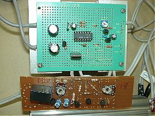
It is a circuit that the substrate above charges the battery with by the constant voltage. This remodeled and made autumn "Regulator 723 for a highly accurate power supply and fixed voltage of precise class stabilizing supply kit for large current FET use laboratory" of Akizuki-denshi-tsuusyou. Because the voltage descent was large, FET used the transistor. The oscillation of IC is the unmeasures in the photograph.
The substrate below is a substrate that controls the battery drain. It made it from scraps of an experimental hole getting tired substrate. Please do not look too much well. The deep-sea bass is seen.
Combination photograph with inverter
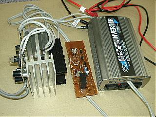
It is a circuit with which it charges the battery of 12V and a circuit discharged with the inverter.
It is a circuit that the leftmost device charges with by the constant voltage. First of all, it is an experiment though the cooling wheel should be large a little more. The thermal resistance only of the cooling wheel is two [ C/W ]. Adhering to right side is a cooling wheel of the diode for the prevention of backflow.
It is a circuit by which the substrate at the center controls the battery drain. It is a device that stops discharging electricity when falling up to the discharge starting and 11.5V when becoming 13V or more. It is a relay that this side is black.
It is an inverter of 300W from which the rightmost device changes 12V of direct current into 100V of the exchange. This is a marketed commodity. It controls by the substrate at the center.
The compulsion fan was installed in the radiator.
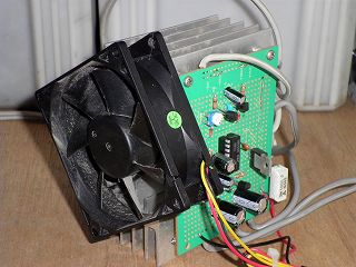
Still, when the amount of power generation becomes the maximum, it becomes hot no touch by the radiator. The radiator was cooled with the compulsion fan though it had used as it is for about eight years.
The fan is DC [burashiresufan] of 8cm corner that became unnecessary for the assembly personal computer. The specification was 12V0.13A.
The cement resistance of 100Ω2W was put in the series, and it installed it in the output of the solar panel in parallel. A white thing in the lower right of this photograph is the cement resistance. This fan cools the cement resistance.
The radiator doesn't become it though it rotates soundlessly quietly ..quite hot... The fan stops when darkening at night. It is very good feeling.
Installation situation and result of solar panel
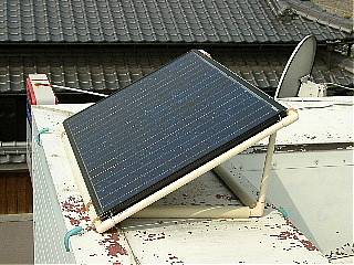
Practical use of solar power generation
It is an installation situation of the solar panel. The surface produced the counter with the iron pipe PVC pipe tubing ..the roof of the shop.. with the pipe made of plastic. The angle was adjusted to 35 degrees aiming at due south.
It is about 40W of about the 1/3 at the mortar cloudy weather level though the power generation of about 120W under the direct sunshine at midday is done. Four parallel batteries for the car of 12V28AH are made and it has used it with about 110AH during about 10 hours/days. The use discontinuance voltage of the battery has been changed to about 11.5V. Operation is excellent according to schedule.