Production of probe adaptor for THS710
Tektronix THS710 Digital Oscilloscopes I had used for many years. Then, with little change in resistance of channel 1. I have become 80% of the original measurements. No problem at all, so I use a 1:1 probe, It is estimated to be only a variation of input resistance.
Not even enough to scope out for repair, I tried to repair it. But I have been using it as it is not degraded.
It thought putting between 10:1 probes and oscilloscopes feeling that it was still inconvenient recently, and making the adaptor of the probe and use as the input of 100:1.
It introduces it because it is unquestionable to use it by the frequency up to about 100kHz though it might be evil ways if it sees from the specialist. Even when the sensitivity of a vertical axis changes with other models, this idea will be able to be used.
Circuit of probe adaptor
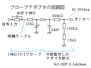
A left circuit is a probe adaptor that I thought about. A left part of this figure is a circuit of the probe of original input resistance 10MΩ10:1. This schematic diagram is my presumption by the one that resolves a broken probe and examined it.
Because it was assumed to use the probe of 10MΩ by the load of 1MΩ, the input resistance of the adaptor was adjusted to about 1MΩ. The attenuation ratio was adjusted to 1/100 as a whole.
The resistance of 12kΩ was decided by cutting and the trial. Moreover, the capacitor of 33PF was decided by cutting and the trial.
It is presumed that the input resistance of channel 1 became about 780kΩ from 1MΩ because measurements became about 80 percent only as for CH1 of the oscilloscope when 10:1 probes are used. It thought the load resistance of the probe suddenly became 90.9kΩ, and was adjusted to 100:1 compulsorily without using the resistance of 820kΩ of this schematic diagram.
It was settled by not going well of the frequency correction in this method of the result of the experiment, and the assumption of the load of the probe after all about 1MΩ. The problem is not in the probe in the translation used on the assumption street if it is this. However, I think that the shape of waves is delayed a little because of the capacitor of 33PF. The shape of waves of quite unquestionable had been in the square wave of 1kHz.
Because it was a difference of the extent that hardly understands compared with CH2, I do not think that there is a problem on practical use though the shape of waves was actually measured by horizontal axis 10μS/DIV level.
For the present, if 1:1 probes and 100:1 that uses this adaptor are used properly by this well, this oscilloscope can be mastered.
Photograph using probe adaptor
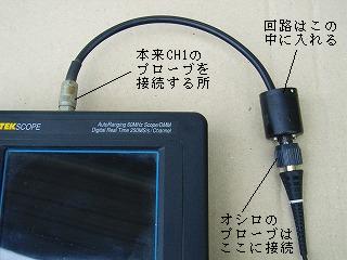
The probe adaptor that this photograph produced is used. The made circuit is put in the shielding case, and put there in the CH1 input of the oscilloscope with 3C-2V coaxial cable of 20cm.