Amplitude modulation wave and easy AM theory
The wireless broadcasting of the medium wave does broadcasting that uses the amplitude modulation. Even if the scale is small, what produced with "Design and production of AM wireless microphone" puts out an almost similar electric wave with the broadcasting station. The AM wireless broadcasting generates high frequency (540kHz-1600kHz) of the medium wave in signal (100Hz-7.5kHz) of the voice and the electric wave for broadcasting has been generated by the amplitude's modulating.
Process of making amplitude modulation wave
This figure shows the process of creating a wave amplitude modulation. (C) the carrier wave (radio wave) waveforms in the time axis, (S) is a single low-frequency signal wave. (D) is the (S) (C) when the AM modulation amplitude modulation waveform. This is similar to an oscilloscope waveform.
Here, the modulation depth indicates the depth of modulation m is as follows.
m = (P-Q) / (P + Q)
Amplitude-modulated spectrum by single audio frequency
The AM and viewed on a spectrum analyzer using a frequency modulated wave looks like this figure. In other words, the voltage E as a carrier, the modulating signal frequency fs [Hz] and. Then the upper and lower carrier fs [Hz] as far away, mE/2 wave upper and lower side-band are as left figure.
Where m is the modulation index of 1. Compared to the size of the carrier wave,upper or lower side-bnd voltage is -6dB. Total power of the upper and lower sideband is -3dB. So 100% modulation power of the modulated wave is 1.5 times.
Amplitude-modulated spectrum by audio frequency
An upper and lower sideband can be done in the top and bottom of the transportation wave frequency when modulating by an actual voice as shown in this figure.
The bandwidth of the broadcasting channel is 15kHz though the channel interval of the broadcasting station of the medium wave (separation) is 9kHz. Therefore, the frequency of the voice becomes this less than 7.5kHz of the half.
The tone quality of the wireless broadcasting of the medium wave is not so good because there is a cause in this broadcasting system compared with the frequency modulation broadcasting.
Any signal is not, and is the one that the electric power is large and is quite useless in this signal carrier though the signal carrier is always launched in the amplitude modulation of the wireless broadcasting of the medium wave as shown in this figure. (There is an advantage that the receiver side becomes easy. )
Moreover, an upper and lower side-band wave is upper and lower, the same, and it is useless one that sends two. It is an electric wave that is called removing this useless one, and the transmission only of a lower side-band wave on SSB. This is used for amateur radio etc. , and a very efficient electric wave form.
AM wireless microphone measured with Spectrum analyzer
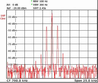
I want to do the design production AM and the one that the output of a wireless microphone was measured with the Spectrum analyzer is this shape of waves.
It is the one that AM wireless microphone was modulated by about 25% in the sine wave of 1.5kHz.
In this horizontal axis, a central frequency is 700kHz, the left end is 687.5kHz, and a right edge is 712.5kHz.
The level of the first upper and lower side-band wave of the plus or minus 700kHz1.5kHz is about -18 a dB compared with 700kHz signal carrier's level, and the theory street. It is for FM modulation element that in top and bottom of the next odd number side-band wave with level difference
The level of about the second side-band wave of the plus or minus 700kHz three kHz is about -40 a dB compared with the level of the first upper and lower side-band wave. I think this to be the one by the linearity of the modulation of the AM modulator and the one by residual FM the modulation element. There is no problem because it is It is 1/100(Correspond to the distortion by 1%), and is an electric power, and however, it is a voltage and 1/10,000 in case of -40 the dB. It is the very difficult generally one that makes to 1% or less at the distortion rate of the synthesis of the AM modulation.
Block diagram of AM wireless microphone
It is a block chart of the AM wireless microphone that this figure produced this time.
It amplifies to the signal of the size only to modulate the audio signal from the microphone by TR1 and TR2.
TR4 has been converted into a low impedance emitter follower. TR5 is a power amplifier is modulated using a collector. The high-power modulators, it is common to use a modulation transformer, where it was a simple series modulator and power because it is small, with no modulation transformer.
TR3 generates the signal carrier in the oscillation circuit of about 700kHz. The modulated high frequency is supplied to the antenna of the lead wire of 1-2m and radiated as an electric wave in the air.