Production of CS satellite changer
Motive and result of production
![]() SKYPerfecTV! of
communication satellite broadcasting is broadcasting by using two satellites
of JCSAT-3 and JCSAT-4A. Therefore, it is necessary to change two satellites to
the direction adjustment of the CS antenna for both satellites.
SKYPerfecTV! of
communication satellite broadcasting is broadcasting by using two satellites
of JCSAT-3 and JCSAT-4A. Therefore, it is necessary to change two satellites to
the direction adjustment of the CS antenna for both satellites.
It was thought that it was possible to make it comparatively easily and I made it by oneself though the change machine (switch container) seemed to be marketed as an accessory of the CS level checker by me. It operates only by making it well, and it finds it useful to the adjustment of the CS antenna very much. I do not know what kind of circuit the marketed commodity is.
If this switch container exists, the adjustment only with the CS antenna is possible before the cable is constructed.
| Signal demanded from CS converter power supply for both satellites | |
|---|---|
|
Send switching signal with satellite power |
Pulse signal of 32-53kHz 0.6Vp-p There is a pulse signal JCSAT-4A. Pulse signal none JCSAT-3 |
|
Power-supply voltage of CS converter |
DC +11V Vertically-polarized wave DC +15V Horizontally-polarized wave |
|
My electric field strength measuring instrument leader 952 can change the power-supply voltage. Therefore, only the generation circuit of the satellite change signal was produced. |
|
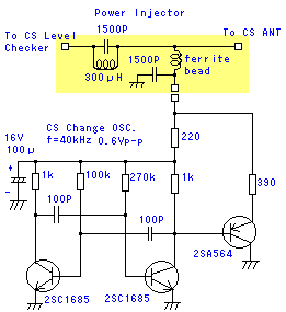
Schematic diagram of satellite power supply insertion and satellite change signal generator

A yellow part of this schematic diagram is a circuit of the satellite power supply insertion machine. This adjusted and used the thing that had been made before. This is used to connect the satellite change signal generator this time. The coil used that the inductor and the ferrite bead of 300μH were passed through the copper wire.
Impedance by 40kHz of 300μH is about 75Ω. Impedance by 40kHz of the capacitor of 1500PF is about 2.7kΩ.
The lower side is a schematic diagram of the satellite change signal signal generator. The power supply uses the power supply of the level checker. It is an astable multivibrator of 40kHz. To decrease current consumption, the ratio ..turning on and off.. has been on purpose changed.
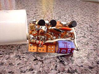
Assembles and encases it

The circuit is put in the useless article of the film case making it on a hole Akino experimental printed wiring board.
It puts it out from the bottom of the film case by installing the coaxial cable on the printed wiring board. The lid is done when completely encasing it.
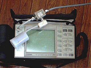
How to use actual.

Detaching of the cable is facilitated previously putting up F type plug.
The usage is adjusted putting up the CS change machine after the CS change machine is removed and it is adjusted to JCSAT-3 to JCSAT-4A. It is adjusted by taking and putting it now to the best point.
The electric field strength measuring instrument is 952 of the leader. This is also very convenient. It is a tiny flaw in a gem that power consumption is large.